Technical Guide
Cooling tower spray nozzles: flow, pattern, clogging
2026-11-14 · Engineering
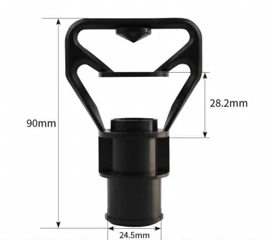
When a counterflow tower loses 1.5–2 °C of approach and the fill comes out clean, the fault is usually a few hundred millimetres above it, in the hot water distribution basin. Nozzles that have lost their pattern, or a header leg that has scaled shut, starve part of the pack and the tower behaves like a unit with 15% less fill area — while every sheet in it is still new.
Re-nozzling is the cheapest thermal recovery available: USD 2–15 per nozzle against USD 95–150 per m³ for a new pack. It fails when the orifice is picked by thread size instead of flow, so here are the deciding numbers.
1. Three values decide whether a nozzle works
Match them to the tower, not the part in your hand:
- Flow per nozzle. 1.0–4.5 m³/h at 0.5 bar covers most HVAC and light industrial counterflow basins, set by an 8–16 mm orifice. Flow follows the square-root law, so doubling header pressure gains 41% flow, not 100%.
- Cone and throw. 90°–120° cones on a 600–900 mm grid, one nozzle per 0.4–0.8 m² of plan area, reaching the fill top face 150–400 mm below the outlet.
- Pattern. Square (target) pattern for a rectangular basin worked on a grid; round or splash pattern where the header runs along one wall and throws across.
Measure, do not trust the label: a 5 L bucket and a stopwatch on three nozzles tells you whether the header runs at 0.3 or 0.6 bar, which explains most "the new nozzles made it worse" complaints.
| Symptom | Probable cause | Check | Fix |
|---|---|---|---|
| Dry patches under one header leg | Orifice undersized, header under 0.25 bar | Bucket test per nozzle | Resize to 0.4–0.6 bar |
| Wet carryover, eliminator dripping | Cone too wide, orifice oversized | Plume and eliminator face | Step down one orifice size |
| Bare strip along the basin wall | Wrong pattern, edge spacing too wide | Pattern map on dry fill | Square pattern, half-spacing at edge |
| Leaks or nozzles dropping out | Thread or snap-fit mismatch | Withdraw three nozzles | Correct 3/4"–1½" BSP or NPT adapter |
2. Balance the header, not only the nozzles
Target ±5% between the first and last nozzle on a leg. That means header velocity under 1.5 m/s and friction loss below 10–15% of nozzle pressure: a 90 m³/h basin needs a DN150 main, not a DN80 from an old drawing. Balance valves set against measured flow beat a wider cone.
Nozzle count follows: at 2.5 m³/(m²·h) loading and 2 m³/h per nozzle, one nozzle serves 0.8 m², so a 6 × 6 m basin takes 45 and a 500 m² basin 600–700. An anti-clogging nozzle set holds ±4% flow across a leg, which keeps the top face of the vertical-flow counterflow pack uniformly wetted.
3. Clogging is a filtration number
Debris above one third of the orifice bridges: 2.5 mm on an 8 mm orifice, 5 mm on a 16 mm one. Three thresholds predict trouble before the tower does:
- Suspended solids above 50 mg/L with a 10 mm orifice clog a header in 3–6 weeks.
- Hardness above 300 mg/L as CaCO₃ scales a 10 mm orifice shut in 2–4 months at 45 °C basin temperature.
- Strainer. 40–60 mesh (0.25–0.42 mm) upstream, differential alarm at 0.3 bar, a reachable flush port.
Two adjacent dry patches and a 1.0 K approach drift are the warning; once the fill face bleaches white from dried solids, the header has been half blocked for a season.
4. Material, and the replacement window
| Body material | Continuous limit | UV | Where it fits |
|---|---|---|---|
| PP, stabilised | 90 °C | Good | Default for hot basins, 35–50 °C |
| PA-GF (glass-filled nylon) | 100 °C | Good | High-temperature, high-pressure headers |
| ABS | 70 °C | Fair | Cooler basins, indoor plant |
| uPVC | 50 °C | Poor | Cold-side and makeup lines only |
Plan a drain-and-swap, not a shutdown: 15–20 minutes per nozzle with clean threads, 45–60 where scale has locked them; two fitters finish a 300-nozzle basin in two shifts, with parts at USD 600–2,500. Replace the whole set rather than 20% of it — mixed ages mean mixed flow, and mixed flow is the uneven coverage you were curing. The same window is the moment to check the strainer and the universal replacement nozzles that fit older OEM basins without adapters.
Conclusion
Spray nozzle selection is a flow, cone and balance problem: 1.0–4.5 m³/h per nozzle at 0.5 bar, one nozzle per 0.4–0.8 m², ±5% balance across the header, debris under a third of the orifice. Get those four numbers right and a re-nozzle returns 0.5–1.5 K of approach for a fraction of the cost of new fill; get them wrong and the tower performs as badly, with newer parts.
Send the basin plan area, nozzle count, header diameter and measured pressure at the farthest nozzle, and we will return a nozzle schedule, an orifice size and a flow balance target.